Project Description
The main goals of this project are to provide an explanation of topology optimization, instruct usage of a readily available topology optimization software, and to compare two different, currently available softwares. This project was completed during my second semester of graduate school. I was on a team with two other students.
What is Topology Optimizatin?
Topology optimization (TO) is a tool that is becoming more prevalent in the engineering world today. Topology optimization uses finite element analysis (FEA) to evaluate the fitness of a certain design (based on an objective, such as a stiffness to weight ratio) and mathematical methods to arrive at the optimized part design over a series of iterations. In short, topology optimization uses an iterative method to test how a part handles applied loads, and deletes unnecessary material.
Implementation
A piece of this project involved putting together a short tutorial, explaining how to use the topology optimization program that is currently built into Solidworks. For the tutorial and the software comparison, we chose to use a bike fork crown as our part to optimize.
Within the Optimization
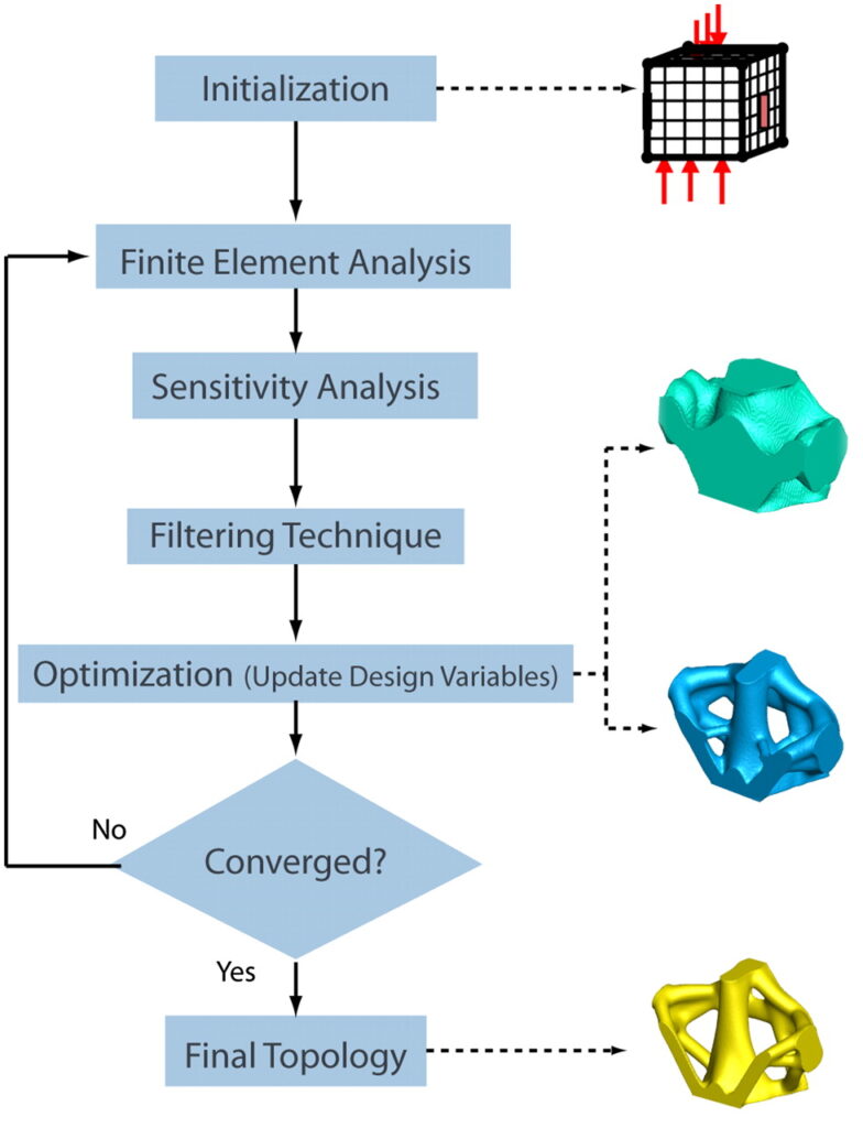
The first step when running a topology optimization is to create a finite element mesh in the design space. Each element in the mesh receives a corresponding stress level and strain energy from the initial study. The solver will use these values to determine the importance of the element to the structure. The solver operates by removing the elements which handle the least amount of stress from the model.
Because the model is tested between each removal of mass, removals that drastically affect the part’s stiffness (mistakes) may be added back to the model. Due to the computational expense of running these simulations, many modern simulations choose not to immediately remove an element from the part. Rather, the stiffness and density of that element is altered. Based on a density threshold, such elements are eventually pushed or pulled to either have material or be void, resulting in an optimized structure comprised of a single material.
Over the course of many iterations, a clear load path will become defined and only the essential regions of the design space remain. The final solution is guided by the initial goals set forth by the user. If the user set the target mass to be 40% of the original design, then 60% of the original elements should be removed.
Challenges Involved
An optimization simulator may use a voxelized representation of the part throughout the simulation. This is a common way of simulating the solid so that voxels can be removed or added accordingly. With this method, the algorithms utilized in topology optimization must have ways of tackling specific challenges.
For starters, checkerboarding must be handled. This is when locations next to one another repeatedly alternate between having material and no material, like a checkerboard, and can result in designs that are not feasible. One method of tackling this issue is presented by Shukla et al. (see references).
Another obstacle that must be handled by the algorithm is converting the voxelized part representation into a watertight mesh that accurately represents the optimized model. Without a watertight mesh (a mesh with no holes), the final part will not be feasible. In the references section of this paper is a link to more in-depth information regarding how this may be dealt with.
One more barrier involved with this type of simulation is making sure that the optimized part does in fact remain one solid part. It is possible, based on preserved regions and loads applied, that an optimal design found by a simulator does not fully connect to itself. Therefore, a check for this situation also needs to be incorporated into the algorithm
Software Comparison
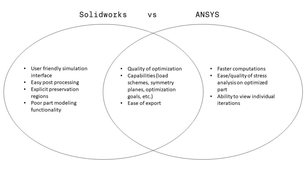
One aspect of this project, as mentioned above, was to compare the functionality of two commercially available topology optimization softwares, ANSYS and SolidWorks. While both softwares utilize the TOSCA optimization engine, some key differences are apparent.
Running a topology study in SolidWorks is fairly simple and intuitive. The process is similar to setting up any other FEA simulation in SolidWorks with a few extra steps such as the design objective and manufacturing controls. One especially convenient feature in these manufacturing controls is the ability to add avoidance regions by selecting a surface and choosing an offset radius. One convenient feature found in Solidworks is a graph that updates during the simulation and shows the convergence of the optimization, allowing for simple monitoring.
One downfall of the Solidworks simulation is an inability to analyze the optimized part with an FEA analysis. This means it is not possible to review the final stress concentrations of the part loads are applied. The simulations in Solidworks also took a fair amount of time to compute (15-20 minutes for a simple part with a standard mesh size).
With the exception of the easily definable preservation regions, ANSYS incorporates the same functionality as Solidworks, with a few added features. Unlike Solidworks, ANSYS is able to perform an FEA analysis on the optimized part from the simulation. ANSYS also allows the user to see images of the part as it is being modified. This means that the user can modify what material is being added or taken away with each iteration. In general, ANSYS also boasts a faster computation speed than Solidworks when comparing two similar optimizations.
Some key pitfalls of the ANSYS software include an inability to select preserved regions, and the presence of a more difficult user interface, both when setting up the simulation and when using the SpaceClaim CAD package to create a part or edit an optimized part. In general, we found that using ANSYS involved a much steeper learning curve than Solidworks, and was still more tedious after the interface became familiar to us.
In Conclusion, the most significant differences between these two software packages lie in their usability and their optimization abilities. Solidworks has a much more user-friendly interface and more readily allows for post-processing of the optimized part. In comparison, ANSYS allows for stress analysis of the optimized design and has significantly shorter computation times.
Post Processing
Topology optimization is not utilized more in today’s industry because the resulting parts can only be produced via additive manufacturing. With Solidworks, the optimized mesh can be easily exported and layered over a separate configuration of the part, allowing the user to use Solidworks to create an optimized but manufacturable part, as seen here.